Mfr Part # ABX00087
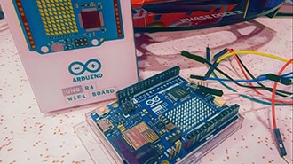
ARDUINO UNO R4 WIFI
Arduino
License: GNU Lesser General Public License Displays LED / Display Drivers LED Matrix Real Time Clocks (RTCs) Arduino
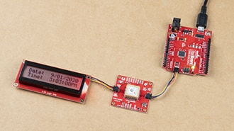
In this Visual Programming Visuino tutorial, we’ll use the Arduino Uno R4 WiFi’s built-in RTC and LED Matrix to create a digital clock without any external hardware.
The built-in RTC (Real-Time Clock) is used to keep accurate time, while the onboard LED matrix displays the hours and minutes directly on the board.
Time data from the RTC is formatted and continuously sent to the LED matrix, updating the display in real time.
Using Visuino’s drag-and-drop interface, you can easily configure the RTC, format the time output, and control how the clock is displayed on the LED matrix.
This project demonstrates how to build a fully functional digital clock using only the Arduino Uno R4 WiFi, making it perfect for quick demos, learning RTC usage, or compact clock projects.
Note: No external RTC module or LED display is required — everything is already built into the Arduino Uno R4 WiFi board.
Watch the Video!


Arduino UNO R4 Wifi
Visuino program: Download Visuino


Start Visuino as shown in the first picture. Click on the "Tools" button on the Arduino component (Picture 1) in Visuino. When the dialog appears, select "Arduino UNO R4 WiFi" as shown in Picture 2


Add "Date/Time Value" component
Add "Decode(Split) Date/Time" component


Select ArduinoUNO R4 WiFi board and in the properties window expand Modules>Display and select Elements and click on the 3 dots button, in the Elements window drag "Text Field" to the left side and in the properties window select "Elements" and click on the 3 dots.
A new Elements window will open. Drag the "Font" element to the left and in the properties, set the font "Adafruit\Picopixel"
Close the "elements" windows
Drag another "Text Field" to the left side and in the properties window set "Y" to 6, select "Elements" and click on the 3 dots.
A new Elements window will open. Drag the "Font" element to the left and in the properties, set the font "Adafruit\Picopixel"
Close all the "elements" windows
Select ArduinoUNO R4 WiFi board and in the properties window expand Modules>Display and set "Orientation" to goRight
Select "DateTimeValue1" and in the properties window set your current time under "Value"
Connect DateTimeValue1 pin [Out] to Arduino Real Time Clock pin [In]
Connect Arduino Real Time Clock pin [Out] to DecodeDateTime1 pin [In]
Connect DecodeDateTime1 pin [Hour] to Arduino Display Text Field1 pin [In]
Connect DecodeDateTime1 pin [Minute] to Arduino Display Text Field2 pin [In]

In Visuino, at the bottom, click on the "Build" Tab, make sure the correct port is selected, then click on the "Compile/Build and Upload" button.
Congratulations! You have completed your project with Visuino. Also attached is the Visuino project that I created for this tutorial. You can download it and open it in Visuino: https://www.visuino.com
Download Visuino file: UNO-R4-Clock.visuino