Mfr Part # A000066
ARDUINO UNO R3 ATMEGA328P BOARD
Arduino
License: General Public License 3D Printing Energy Harvesting / Solar Arduino
This Arduino-based dual-axis solar tracker automatically orients a photovoltaic panel to follow the sun's position throughout the day, maximizing energy collection efficiency. Using four light-dependent resistors (LDRs) arranged in a cross configuration and two servo motors, the system achieves continuous real-time sun tracking along both horizontal (azimuth) and vertical (elevation) axes.
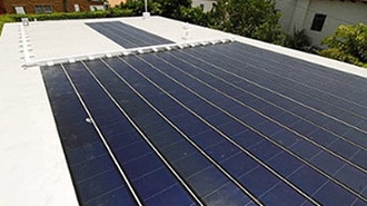
The tracker can increase solar energy output by up to 40% compared to fixed-mount installations by maintaining optimal panel alignment from sunrise to sunset.
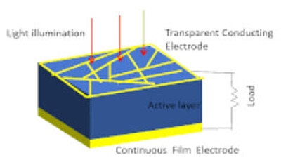
A dual-axis solar tracking system adjusts a solar panel's orientation along two rotational axes—azimuth (east-west) and elevation (north-south), enabling the panel to track the sun's apparent motion across the sky. Unlike fixed installations or single-axis trackers that only follow one dimension of solar movement, dual-axis systems maintain perpendicular alignment with incoming sunlight throughout daylight hours.
The system employs LDR sensors to measure light intensity from multiple directions. An Arduino microcontroller processes these readings and commands servo motors to adjust the panel position, ensuring the surface remains oriented toward the brightest light source.
System Design
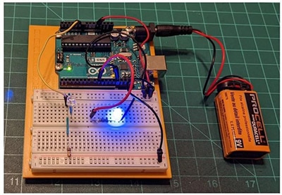
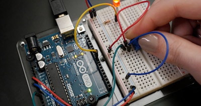
The circuit architecture centers on an Arduino UNO microcontroller that orchestrates two servo motors for dual-axis rotation. Four LDR photoresistors are positioned in a quadrant arrangement to detect light intensity from top, bottom, left, and right directions.
Each LDR pairs with a 10kΩ resistor to form a voltage divider circuit, converting light intensity variations into analog voltage signals that the Arduino can read. The microcontroller analyzes these sensor inputs to calculate the brightest light direction and commands the servo motors to adjust panel orientation accordingly.
Key Circuit Features:
Quadrant Sensor Array: Cross-configured LDRs enable omnidirectional light detection
Voltage Divider Networks: 10kΩ resistors paired with each LDR provide stable analog readings
Independent Servo Control: Separate motors for X-axis and Y-axis positioning
Analog Inputs: Channels A0-A3 dedicated to LDR sensor readings
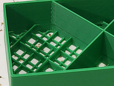
The mechanical structure was fabricated using 3D-printed components for precise alignment and stable motion control. All structural parts were designed to accommodate servo motor mounting while allowing a full range of motion along both tracking axes.
The 3D models utilized in this build were sourced from published reference designs, ensuring proper mechanical tolerances and servo integration points. The printed assembly includes:
Base platform with horizontal servo mount
Vertical rotation bracket
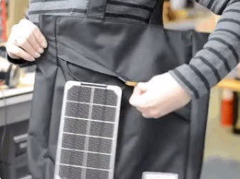
Solar panel mounting frame
LDR sensor housing with quadrant positioning
The control firmware continuously monitors all four LDR sensors and adjusts servo positions to track the brightest light source. The program implements noise reduction through averaging and includes low-light standby functionality.
Two servo objects control independent axis movement with defined angle limits to prevent mechanical over-rotation:
Servo horizontal;
Servo vertical;
Four LDRs monitor light intensity from each cardinal direction:
int ldrlt = A0;  // Top-left
int ldrrt = A3;  // Top-right
int ldrld = A1;  // Bottom-left
int ldrrd = A2;  // Bottom-right
The firmware implements averaging to reduce sensor noise and improve tracking stability:
int readAverage(int pin) {
  long total = 0;
  for (int i = 0; i < 10; i++) {
    total += analogRead(pin);
    delay(2);
  }
  return total / 10;
}
This function samples each LDR ten times and returns the mean value, effectively filtering transient fluctuations.
The controller calculates average light intensity for each axis by combining readings from opposing sensors:
int avt = (lt + rt) / 2;  // Top average
int avd = (ld + rd) / 2;  // Bottom average
int avl = (lt + ld) / 2;  // Left average
int avr = (rt + rd) / 2;  // Right average
When the difference between opposing sensors exceeds a tolerance threshold, the corresponding servo incrementally rotates toward higher light intensity:
if (abs(dvert) > tol) { /* Adjust vertical servo */ }
if (abs(dhoriz) > tol) { /* Adjust horizontal servo */ }During darkness or extremely overcast conditions, the system enters standby to conserve power and prevent unnecessary servo activity:
if (avgLight < 200) {
  Serial.println("Low light detected — Tracker on standby...");
  return;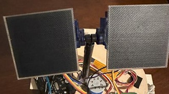
}The dual-axis solar tracker operates through continuous comparative analysis of light intensity across four sensing quadrants. When one sensor detects higher illumination than its opposing counterpart, the Arduino commands the appropriate servo to rotate the panel toward that direction.
The horizontal servo manages east-west positioning (azimuth control), while the vertical servo handles north-south tilt (elevation control). This biaxial adjustment maintains optimal panel-to-sun alignment as solar position changes throughout the day.
Light Sampling: All four LDR sensors simultaneously measure incident light intensity
Data Processing: Arduino averages readings and computes horizontal and vertical light differentials
Decision Logic: The System determines the required movement direction when differentials exceed the tolerance threshold
Servo Actuation: Motors rotate to new positions based on calculated corrections
Continuous Monitoring: Process repeats at regular intervals throughout daylight hours
This closed-loop feedback system ensures the panel maintains perpendicular alignment with direct solar radiation, maximizing photon capture efficiency regardless of time or season.
The system demonstrates an active response to light source position changes. When illumination shifts in any direction—left, right, upward, or downward—the tracker immediately adjusts panel orientation to maintain alignment with the brightest point.
The tracking response is smooth and incremental, with the servo motors making small angular corrections rather than large sudden movements. This gradual adjustment approach reduces mechanical stress and power consumption while maintaining accurate sun following.
This dual-axis solar tracker system, using an Arduino system, represents an effective approach to maximizing photovoltaic energy capture. By employing simple LDR sensors and servo motors under microcontroller command, the design significantly improves power generation compared to static and single-axis installations.
The system's modular architecture, utilizing readily available components and 3D-printed mechanical elements, makes it accessible for makers and engineers interested in renewable energy optimization. The intelligent tracking algorithm, combined with low-light standby functionality, demonstrates how affordable electronics and smart programming can dramatically enhance solar panel efficiency.
For those exploring solar energy projects, this dual-axis tracker showcases the practical implementation of automated sun-following technology that directly translates to measurable energy gains.