Buck Converters Simplify Energy Harvesting from High-Input-Voltage Transducers
Electronic Products 제공
2013-05-08
In certain energy-harvesting applications and operating conditions, transducers such as piezoelectric devices can produce high output voltages well above typical operating levels. In these cases, a step-down, or buck, converter offers a simple choice for maximizing transducer power output. For these types of high-input-voltage energy sources, engineers can implement efficient energy-harvesting solutions using available buck converters from Linear Technology, Maxim Integrated, and Texas Instruments, among others.
A buck converter comprises an inductor along with a pair of capacitors and switches designed so only one switch is on at any time. Simply put, when switch A is open, switch B is closed, and vice-versa (Figure 1). In operation, the switches alternate, causing current to flow to the inductor or to ground. When switch A is on, switch B is off and current flows from VIN to the inductor. When switch A is off, switch B is on and the inductor is connected to ground, so energy stored in the inductor is discharged into the load.

In continuous conduction mode (CCM), the inductor current never drops to zero, while in discontinuous conduction mode (DCM), the inductor current can drop to zero. Buck converters that use FETs such as illustrated in Figure 1 are called synchronous buck converters; nonsynchronous buck converters use a Schottky diode for switch B. Because a FET has a lower voltage drop than a Schottky diode, synchronous buck converters are generally more efficient.
For energy-harvesting applications that operate with higher input-voltage levels, buck converters offer a convenient solution for maximizing power output from transducers. High-output-voltage transducers with linear source impedance such as piezoelectric devices operate with a characteristic power curve (Figure 2).

To maintain maximum power output, the transducer must be operated at a load impedance that matches its source impedance – an operating voltage that is typically half of the device's open-circuit voltage. In practice, however, this operating point, called the maximum power point (MPP), varies in response to changes in its operating environment, including changes in the nature of the energy source, temperature, and mass loading of the piezoelectric device itself.
With a buck converter, engineers can set the transducer's load impedance by setting the converter's switching frequency and inductor size, and alter it dynamically by changing the duty cycle to maintain maximum power output from the piezo device. Combined with a full-wave rectifier bridge, a synchronous converter can extract maximum energy from the AC voltage generated by the piezo device as it deflects in both directions away from its neutral point.
The choice of inductor is a critical issue for proper operation of a buck converter. Typically, engineers can find the specific recommended inductor size – or size range – from the manufacturer's datasheet. For its LTC3632 synchronous buck converter, Linear Technology recommends setting the inductor value according to Equation 1 below, subject to the constraint of Equation 2.

where: VOUT = output voltage
VIN = input voltage
f = switching frequency
IPEAK = peak current trip threshold

where:
VIN(MAX) = maximum input supply voltage for the application
IPEAK(MAX) = maximum allowed peak inductor current
tON(MIN) = 100 ns
In general, larger inductor values allow use of lower switching frequency and result in higher efficiency but present a larger footprint in the final design compared to use of lower inductor values.
Available buck converters such as the Maxim Integrated MAX638, Linear Technology LTC3632, Linear Technology LTC3388, and Texas Instruments TPS62120 offer a simple solution for stepping down input voltages to typical operating voltage levels (Figure 3).

Along with the typical pair of capacitors and an inductor, buck converters in this class typically use a pair of resistors to divide the output current down for comparison with an on-chip voltage reference - 800 mV in the case of the LTC3632. For the LTC3632, if the voltage at VFB is greater than the reference, the comparator activates a sleep mode in which the power switches and current comparators are disabled, reducing the VIN supply current to only 12 μA.
The Texas Instruments TPS62120 is a synchronous buck converter intended for energy-harvesting applications, supporting an input voltage range of 2 to 15 V while providing up to 75 mA output current. Similar to the Linear LTC3632, the TI TPS62120 uses an on-chip 800 mV reference to switch to a low-power sleep mode. To maintain high efficiency with light loads, the TI converter uses a hysteretic PFM/PWM controller scheme, where the device operates in PWM mode at high loads and automatically switches to PFM mode in light loads, where it consumes only 10 μA quiescent current from VIN. Besides maintaining efficiency across different loads, the use of this PFM/PWM scheme permits the use of ceramic capacitors, which offer low series resistance and result in low-output-voltage ripple.
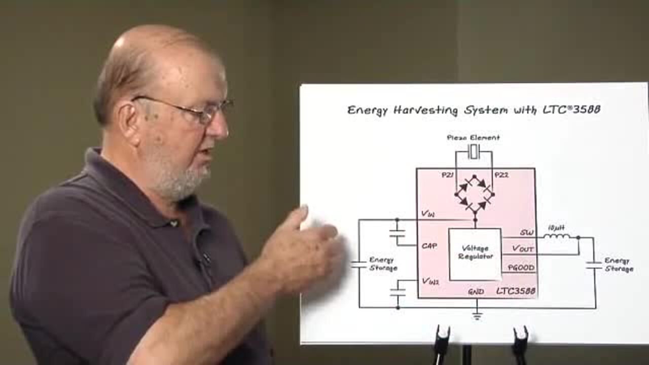
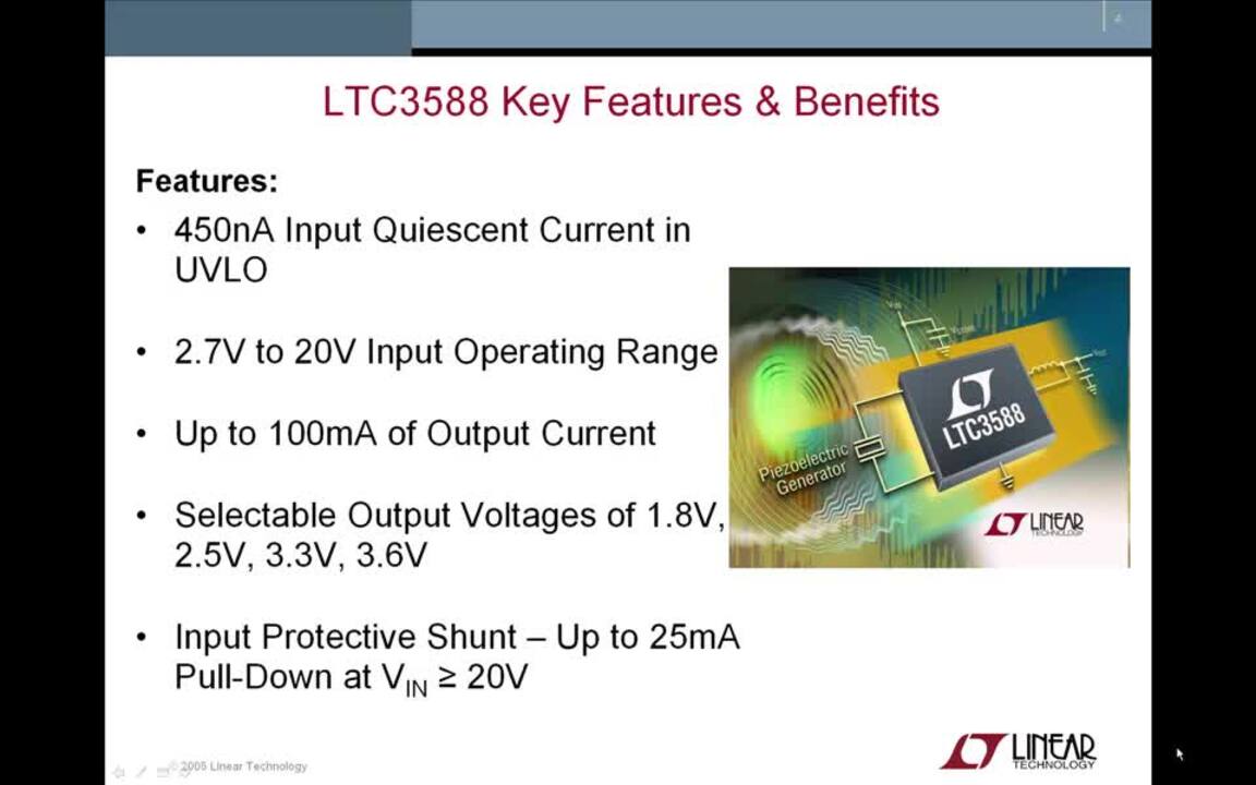
Designed specifically as a piezoelectric energy-harvesting power source, the Linear Technology LTC3588-1 extends the Linear LTC3388 buck regulator with specialized on-chip features. The LTC3588-1 integrates a low-loss full-wave bridge rectifier with a buck converter to provide a complete piezoelectric energy source with only the usual complement of external components required for a buck converter (Figure 4).

Capable of delivering up to 100 mA of continuous output power at multiple selectable output voltages, the LTC3588-1 features a quiescent-current undervoltage lockout (UVLO) mode with a wide hysteresis window. While in UVLO mode, the LTC3588-1 draws only 450 nA, allowing charge to accumulate on an input capacitor until the buck converter can efficiently transfer a portion of the stored charge to the output. In regulation, the LTC3588-1 enters a 950 nA low-power state, switching the buck converter on and off as needed to maintain regulation.
Conclusion
Buck converters offer a simple solution to specialized energy-harvesting applications with high-input-voltage levels. Available buck converters typically require only a pair of capacitors and an inductor to implement an efficient DC/DC converter. Specialized versions of available buck converters offer a highly integrated solution for building efficient energy-harvesting circuits powered by piezoelectric devices.
면책 조항: 이 웹 사이트에서 여러 작성자 및/또는 포럼 참가자가 명시한 의견, 생각 및 견해는 DigiKey의 의견, 생각 및 견해 또는 DigiKey의 공식 정책과 관련이 없습니다.