Low-Cost, Power Efficient EMG Prosthetic Hand (Part 2)
2026-05-06 | By Antonio Velasco
Creating a low-cost prosthetic arm is challenging, but making one that is also easy to calibrate and accurate is even tougher. In my previous blog, I talked about how my group is working on an EMG-controlled hand for my senior design project at UC Irvine. I went over the overall concepts and how it’d work. Now, let’s talk about the technical details behind the software and the implementation.
Software Structure
The software is split into two parts: the calibration application and the embedded software. The calibration application’s purpose is to guide the user through the calibration process while communicating with the embedded device. It will also display telemetry in the future, as well as classification results. The UI and flow of the tool were initially designed using a wireframe in Figma, shown here:
")
After initial prototyping, the calibration application was developed in Visual Studio 2022 using C#. The application will automatically pair with the embedded device, given that it is connected to a COM port. Once it is connected, it will follow the user through a series of calibration steps, which involve displaying a gesture for the user to attempt to recreate. During each step, it will send a start message to the embedded device, which will signal it to begin recording data. After a time period, it will send an end message to signal to end recording and store the data. The homepage of the application is shown below.
")
Embedded Software Stack
The embedded software is also abstracted into different parts. It will be written using PlatformIO on Visual Studio with C17. The initial design for the embedded software system and loop can be seen here:
") Initial data flow and design of embedded software
Initial data flow and design of embedded software
The basic flow of data is as follows: the microcontroller receives ADC data at a high rate, filters it, and loads it into a static buffer. After a period of time, a fast-fourier transform is performed on the buffer and used to produce a spectrogram (time vs. frequency). This spectrogram is then passed as input to a convolutional neural network (CNN) for classification into one of the predefined gestures. The classification output is interpreted by the microcontroller and seen as actuation of the fingers.
To handle the varying tasks defined above, FreeRTOS 202406.04 LTS is being used on the microcontroller. The RTOS will be implemented as defined here:
") RTOS diagram detailing data flow between tasks and ISRs
RTOS diagram detailing data flow between tasks and ISRs
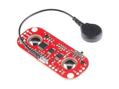
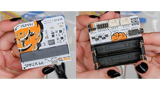
The electrical hardware centers around an STM32 as the microcontroller and primary processing unit. A surface electrode is used to capture EMG signals from the user, whether at the forearm or at the wrist, providing an initial analog input that is reflective of extremity movement. The STM32 has a high-speed, 12-bit ADC and samples at around 500Hz.
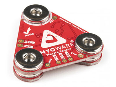
These signals are then routed through a signal processing board via an aux input. The board amplifies, filters, and rectifies the signal to turn the extremely weak and noisy EMG input into clean, interpretable data. Filtering via envelope detection will be done to correct actuation on the outputs. This requires additional calibration for each individual, as EMG signals will vary.
The signal output from the board is then delivered to and interpreted by the STM32, which then controls the actuators via pulse width modulation (PWM).
Next Steps & Initial Results
After implementing the software and doing initial testing with the electrodes, we started to classify and characterize hand gestures, generating the following spectrograms:
")
While we were able to get this started, we’re having issues distinguishing between gestures and actuating all of our servos. In the next blog, we’ll cover all of the troubleshooting steps we took and the physical fabrication of the arm. Stay tuned!