MEMS Oscillators Challenge Quartz Crystals in RF Applications
Electronic Products 제공
2014-10-30
With very few exceptions, every electronic circuit needs an oscillator, also referred to as a clock, clock generator, or timing circuit. Its role is to provide the “heartbeat” for the processor, memory functions, communications ports, A/D and D/A converters (if any) and many other functions. In non-critical, low-budget situations such as $10 mass-market electronic thermometers, this clock may be made from a simple resistor/capacitor (RC) oscillator. However, for the vast majority of situations which are more critical, the oscillator is based on a quartz crystal (Figure 1). This is a mature (80+ years) and highly effective technology which can support of wide range of frequencies from kHz to hundreds of MHz, with performance spanning fairly good to excellent, depending on the crystal cut, fabrication, packaging, and other considerations.

Figure 1: The venerable quartz crystal (but not the entire oscillator) is represented by a standard schematic symbol; b) the equivalent circuit starts with the simplified model shown, but can get much more complicated as operating frequency increases.
However, crystal advances have reached a plateau, while demands on the timing function’s performance, size, cost, and integration are increasing. To meet these needs, a new and disruptive approach is starting to encroach on quartz devices, based on silicon MEMS (microelectromechanical systems) technology which can provide quartz-level performance, and at a performance and cost level which is suitable for many applications. MEMS devices are already highly developed and used in high volume for sensing pressure, motion, and acceleration, and they are now being extended to a new role.
The demands on the timing function are especially challenging in RF applications, where the oscillator is not just a clock for the processor and where a little jitter is tolerable. In RF, it establishes basic carrier/channel tuning at hundreds of MHz and into the GHz range, to ensure proper clocking of the A/D and D/A converters. For converters, any jitter transforms into converter noise and distortion, and so is a critical specification in RF designs.
Oscillator operation
The structure and operation of a crystal timing device is based on the long-known piezoelectric principle, whereby an electrical signal induces stress in a crystal, and the reverse is true as well: applied stress causes the crystal to generate a minute voltage. By using a tiny slab or blank of quartz along with a suitable circuit, the quartz acts as a tuned resonator to provide precisely-spaced clocking signals for the entire electronic system.
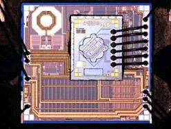
In a MEMS-based device, a radically different approach is used. The etched silicon at the core of the die acts like a tuning fork which resonates at the desired frequency, while additional electronic circuitry on the die manages and amplifies this clock signal (Figure 2).

Figure 2: MEMS oscillator technology uses a version of a tuning-fork-like resonator etched into the silicon, plus support circuitry. (Courtesy of SiTime)
There are dozens of first-, second-, and even third-tier parameters which are used to assess any oscillator, whether crystal or other. The required minimum or maximum values depend on the application, of course, but the relative weighting of these parametric varies with the design.
Key parameters include nominal operating frequency, absolute accuracy, aging-related stability, short- and long-term drift (temperature coefficient and compensation), jitter, operating temperature range, packaging and size, operating voltage, supply sensitivity, power dissipation, shock/vibration resistance, start-up time, vender variations, and cost, to cite a few. Most of these are legitimately measured in different ways and under different conditions, depending on both the application demands as well any historical context.
MEMS advantages and realities
A quartz-crystal-based oscillator is assembled from multiple parts, including the carefully cut and polished quartz blank, the mounting which holds it in the package while also providing electrical contact (and some shock/vibration resistance), and the housing package itself (for more background see the CTS Product Training Module “Crystal Clock Oscillators”). In contrast, a MEMS oscillator is an IC, made on standard-process CMOS production lines, using 8-inch wafers in most cases. After probing, trimming, and testing, the device is packaged; again, just like any IC. Thus, the MEMS device benefits from the mass-production batch techniques and processes used for conventional ICs. (For additional background on MEMS oscillators see the Abracon Product Training Module on its ASFLM1 series). Other advantages of MEMS-based devices include:
- The final device is smaller than the quartz version. This not only saves precious PC board real estate, but it allows the timing device to be placed closer to the device it is supporting, for better signal integrity and reduced EMI.
- The MEMS oscillator can have active circuitry built onto the die, which can be used for compensation circuitry which improves performance versus temperature or supply rail variations. It can also be used to provide the complete oscillator function, as neither a quartz crystal nor a MEMS resonator is a complete oscillator by itself (although the term is often used that way); each needs some associated circuitry to drive the core timing element and condition/scale the output. Many oscillators also need PLL to multiply the base oscillator frequency to the desired carrier frequency, and this, too, can be part of the IC.
- The complete MEMS oscillator core, oscillator circuitry, and interface are lower power than an equivalent quartz function.
- Additionally, work is being done to allow co-packaging of the MEMS device’s die with the IC which it drives (such as A/D converter) in the same way that memory ICs are now stacked and co-packaged with their microcontroller or microprocessor. This would offer multiple benefits: less board real-estate needed, simplified BOM, improved single integrity, and tested and guaranteed performance of the oscillator plus converter without concern for PC- layout issues (which are challenging and often frustrating in the GHz range of RF circuits).
Given all these advantages, there are several reasons why MEMS devices have not displaced crystals oscillators:
- The performance of available MEMS devices may not yet meet requirements in specific applications.
- RF designers are fairly cautious, as the timing function is so critical to system performance.
- While crystals have their shortcomings and artifacts, these are reasonably well understood. In contrast, the subtleties and vagaries of MEMS devices are only starting to be known to the level that RF designers can accept leading-edge designs.
- New RF designs usually incorporate one or a few new-to-market components, such as high-performance LNAs or A/D and D/A converters, but designers are reluctant to try too many new components. It’s about risk management and how many unfamiliar devices the designer is comfortable with using at once, even if each one is potentially beneficial.
- Cost, of course: as a mature technology, crystal vendors have managed to bring costs down through experience and volume. While MEMS devices offer potential for lower cost, this has to be judged on a case-by-case BOM basis.
MEMS oscillators become off-the-shelf standard parts
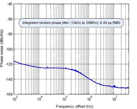
Some available MEMS timing devices illustrate the capabilities of these components. For example, the SiTime SiT8209 high-frequency, ultra-performance oscillator (Figure 3) can be ordered for any frequency between 80.000001 and 220 MHz, accurate to six decimal places. For transitional convenience, it is packaged as a pin-for-pin drop-in replacement for quartz-based oscillators, and features ultra-low- phase jitter of just 0.5 psec, along with frequency stability as low as ±10 ppm. Additionally, SiTime offers many other series of MEMS devices suitable for differing application design requirements.

Figure 3: The SiTime SiT8209 offers extremely-low jitter, critical to many communication applications; the plot shown is the phase noise at 156.25 MHz when operating at 3.3 V with LVCMOS outputs.
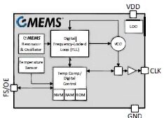
Silicon Labs offers four series (Si501, Si502, Si503, Si504) whose members differ in extra features, with guaranteed performance of 10 years of frequency stability including solder shift, load pulling, supply variation, operating-temperature range, vibration and shock; the vendor claims this is 10× the guarantee of comparable quartz devices. The units provide any frequency between 32 kHz and 100 MHz, and frequency-stability options include ±20, ±30 and ±50 ppm across commercial (-20⁰C to 70⁰C) and industrial (-40⁰C to 85⁰C) temperature ranges. The four-lead devices (Figure 4) operate with any supply rail between +1.71 V to +3.63 V.

Figure 4: Members of the Si501/2/3/4 family from Silicon Labs have the same basic performance specifications, but differ in availability of extra functions such as output enable and frequency select.
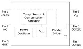
The Micrel MEMS oscillator units from Micrel (Figure 5) are available from 2.3 to 460 MHz operation (the DSC1123, for example, has a 156.25 MHz frequency). Typical RMS phase jitter is below 1 psec, while stability can be ordered with ±10, ±25, or ±50 ppm ratings. The LVDS-output devices are available in 2.5 × 2.0, 3.2 × 2.5, 5.0 × 3.2, and 7.0 × 5.0 mm packages to fit existing footprints, and require a 2.25 to 3.6 V supply. The vendor claims MTF (mean time to failure) is 20 times better than quartz devices.

Figure 5: Micrel’s DSC units are “drop-in” replacements for standard 6-pin LVDS quartz crystal oscillators; devices differ only in the use of the Enable control pin.
Summary
It is difficult to predict to what extent MEMS-based timing devices will displace the long-established quartz-based crystal units in RF designs, and how long this transition will take. There is no doubt that the benefits of MEMS units and their future potential virtues in performance, size, cost, and packaging make them very attractive competition at lower frequencies and increasingly into the higher RF spectrum. Market research firm IHS recently predicted that over a billion MEMS timing units will be shipped in 2016, primarily for mobile handsets and consumer electronics. Vendors see the opportunity, the MEMS technology is already in mass-market use, it is advancing and maturing, and users welcome the benefits as long as any trade-offs – which obviously will vary with the application – are acceptable.
For more information on the parts discussed in this article, use the links provided to access product information pages on the DigiKey website.
면책 조항: 이 웹 사이트에서 여러 작성자 및/또는 포럼 참가자가 명시한 의견, 생각 및 견해는 DigiKey의 의견, 생각 및 견해 또는 DigiKey의 공식 정책과 관련이 없습니다.


