보다 스마트한 고정형 로봇을 위해 감지, 연결, 모션 제어 장치의 고급 기능 적용
DigiKey 북미 편집자 제공
2025-11-18
종종 다축 로봇이라고도 하는 실장형(고정형) 로봇 시스템은 지정된 작업 공간 내에서 고정밀도, 고성능 모션을 제공하도록 설계되었습니다. 이러한 시스템은 반복성, 속도, 페이로드 용량이 중요한 현대 제조 및 자동화 셀의 근간을 형성합니다.
일반적인 예로는 협동 로봇(코봇), 관절형 로봇 암, 선택적 컴플라이언스 관절형 로봇 암(SCARA), 델타(병렬 링크) 메커니즘뿐만 아니라 컴퓨터 수치 제어(CNC) 및 갠트리 스타일 기계가 있습니다. 응용 요구 사항에 따라 이러한 로봇은 레일, 벽, 천장, 플로어에 실장되거나 생산 기계에 직접 통합되어 조립, 재료 취급, 포장, 검사 및 기계 가공 공정을 위해 유연하게 배치할 수 있습니다.
고급 구동 전자 부품, 정밀 센서, 실시간 제어 아키텍처를 통합하는 이 실장 로봇 플랫폼은 스마트하고 연결된 제조 환경에 필수적인 신뢰성, 다목적성, 기능성 및 정확도를 제공합니다. 그러나 이러한 시스템의 이점과 성능을 극대화하기 위해 설계자는 모션 검출, 위치 및 영역 감지, 모션 제어, 연결성 분야의 최신 발전 기술을 이해하고 적용해야 합니다.
이 기사에서는 고급 로봇의 설계 요구 사항을 간략하게 검토합니다. 그런 다음, 설계자가 이러한 시스템을 구현하는 데 사용할 수 있는 Analog Devices의 예시 솔루션과 관련 평가 키트를 소개합니다.
고급 로봇의 설계 요구 사항
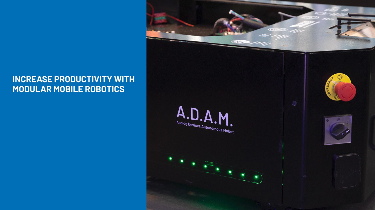
고급 고정형 로봇(그림 1)은 모바일 로봇과 비교하여 두 가지 분명한 차이점이 있습니다. 고정형 로봇은 상대적으로 정적이고 전체적으로 잘 알려진 환경 내에서 작동하며 배터리 전력으로 제약되지 않습니다. 그러나, 변화하는 환경에서도 속도, 정밀도, 반복성, 정확도를 유지하며 작동해야 합니다. 예를 들어, 다양한 크기, 모양, 무게, 방향 및 위치의 패키지를 픽업하고 이동하는 벨트에서 정확한 위치에 배치해야 할 수 있습니다. 이를 위해, 이러한 로봇은 상황을 자율적으로 평가하고 동적으로 적응하면서 자신의 설정과 주변 상황에 대한 인식을 유지해야 합니다.
 그림 1: 잘 알려지고 흔히 볼 수 있는 고정형 로봇은 이제 극도의 정밀도, 유연성, 적응성을 제공합니다(이미지 출처: Analog Devices Inc.).
이러한 요구 사항은 엔드 이펙터를 위한 정밀한 모션 제어, 주변 환경 인지를 위한 ToF(비행 시간) 이미징, 모션 감지를 위한 위한 IMU(관성 측정 장치), 안정적인 고속 통신을 위한 GMSL(기가비트 멀티미디어 직렬 링크)을 신중하게 통합하도록 합니다.
1: 엔드 이펙터 그리퍼를 위한 모션 제어: 로봇 그리퍼는 팔 또는 클램프의 역할을 수행하며 요청 시 열리고 닫힙니다. 로봇 그리퍼는 페이로드에 손상을 주지 않으면서 단단한 그립을 유지할 수 있도록 적절한 크기의 힘을 사용해야 합니다. 그렇게 하려면 정밀하고 균일하며 매끄러운 작동을 위해 모터를 세심하게 조절하는 모터 구동기가 필요합니다. 구동기는 또한 무게 및 공간 제약 사항으로 인해 가볍고 콤팩트해야 합니다.
이러한 컨트롤러에 적합한 솔루션 중 하나로 TMCM-1617 단일축 서보 구동기를 들 수 있습니다(그림 2). 24g의 무게와 36.8mm × 26.8m × 11.1mm 크기를 갖는 이 3상 BLDC(브러시리스 DC) 모터 구동기는 최대 18A RMS를 공급할 수 있으며 8V ~ 24V 전원 범위에서 작동합니다.
") 그림 2: 가볍고 콤팩트한 Analog Devices TMCM-1617 서보 구동기는 완전한 8V ~ 24V, 18A BLDC 모터 제어를 제공합니다(이미지 출처: Analog Devices Inc.).
그림 2: 가볍고 콤팩트한 Analog Devices TMCM-1617 서보 구동기는 완전한 8V ~ 24V, 18A BLDC 모터 제어를 제공합니다(이미지 출처: Analog Devices Inc.).
TMCM-1617은 위치 피드백을 위한 증분식 인코더와 디지털 홀 효과 센서를 지원해 다양한 부하에서 정밀도 및 반복성을 향상시킵니다. 이 제품은 연결성을 위해 CAN, RS-485, EtherCAT 버스 옵션을 제공합니다.
TMCM-1617 및 해당 알고리즘을 빠르게 평가하고 조정할 수 있도록 Analog Devices는 TMCM-1617-GRIP-REF 그리퍼 참조 설계를 제공합니다. 이 개방 소스 하드웨어 참조 설계는 로봇 그리퍼에 사용되는 24V BLDC 모터를 정밀하게 제어할 수 있도록 맞춤화되어 있습니다. 이 참조 설계는 정밀 FOC(자속 기준 제어)를 제공하여 토크 리플을 최소화하고 효율적인 고성능 모터 제어를 가능하게 합니다. 사전 구성된 소프트웨어 스택은 초기 설정 프로세스를 간소화하여 제품의 시장 출시 시간을 단축할 수 있습니다.
2: ToF 센서: 로봇이 주변 환경과 작업 영역 내 물체를 완전히 인지하도록 보장하기 위해, 설계자는 두 가지 기본적인 방법을 사용합니다. 하나는 ToF 감지 구성을 사용하는 것이고 다른 하나는 한 대 이상의 비디오 카메라를 사용하는 것입니다. 각 방법마다 상대적인 이점과 단점이 있습니다.
일반적으로 ToF 카메라는 깊이 감지에 선호되며 높은 정확도로 거리를 측정합니다. 그러나 일반적으로 일반 비디오 카메라보다 공간 해상도가 낮으며, 주변광 및 반사 표면에 의해 영향을 받을 수 있습니다. 반면, 표준 비디오 카메라는 고해상도 이미지를 제공하며 다양한 응용 분야에 다목적으로 활용할 수 있지만, 깊이 정보를 추출하려면 더 복잡한 프로세스와 여러 대의 카메라가 필요합니다.
여러 로봇 응용 분야에 대해 ToF 기반 이미징의 이점은 매우 큽니다. 그러나 ToF 기반 감지 서브시스템은 매칭된 LED 광원, 렌즈, 광학 필터, 이미저를 포함한 많은 전기 광학 부품을 신중하게 통합해야 합니다. 이러한 부품을 선택하고 조립하려면 전기, 기계, 광학 분야에 걸친 폭넓은 전문 지식이 필요합니다.
이러한 어려움을 최소화하기 위해 Analog Devices는 ADTF3175 ToF 모듈을 제공합니다(그림 3). 이 완전한 장치는 1MP(메가픽셀) CMOS 간접 ToF 이미저를 내장하고 있습니다. 또한 이미저용 렌즈와 940nm 광학 대역 통과 필터, 광학계를 포함한 적외선 조명원, 레이저 다이오드, 레이저 다이오드 구동기 및 광 검출기, 플래시 메모리, 로컬 전원 전압을 생성하기 위한 전력 조정기를 통합하고 있습니다.
") 그림 3: ADTF3175 모듈은 완전한 ToF 서브시스템을 구현하는 데 필요한 모든 전기, 기계, 광학 소자를 포함하고 있습니다(이미지 출처: Analog Devices Inc.).
그림 3: ADTF3175 모듈은 완전한 ToF 서브시스템을 구현하는 데 필요한 모든 전기, 기계, 광학 소자를 포함하고 있습니다(이미지 출처: Analog Devices Inc.).
1024 × 1024픽셀 ADTF3175 센서(75° × 75° 시야각(FOV))가 출력하는 이미지 클라우드 데이터는 레인당 1.5Gbit/s로 작동하는 4레인 MIPI(모바일 산업 프로세서 인터페이스) CSI-2(카메라 직렬 인터페이스 2)를 통해 호스트 시스템으로 전송됩니다. 이 모듈의 프로그래밍 및 작동은 4선 SPI(직렬 주변 장치 인터페이스)와 I2C 인터페이스를 통해 제어됩니다. 깊이 범위는 0.4m ~ 4m이며 전체 깊이 범위에서 ±5mm의 깊이 정확도를 지원합니다
연결된 ADSD3500 깊이 이미지 신호 프로세서는 ADTF3175에서 출력되는 메가픽셀 해상도 원시 데이터를 변환하여 최종 반경 방향 깊이, AB(능동 휘도), 신뢰도 데이터 프레임을 생성합니다. 이는 높은 프레임 레이트에서 낮은 지연 시간을 보장하여, 카메라가 빠르게 움직이는 물체를 정밀하게 포착하고, 로봇이 동적으로 변화하는 산업 환경에서 적시에 의사 결정을 내리고 정확한 분석을 수행할 수 있도록 합니다.
모듈의 설정 및 구현을 용이하게 하기 위해 Analog Devices는 EVAL-ADTF3175D-NXZ 3D ToF 센서 평가 키트를 제공합니다(그림 4). 이 오픈소스 키트에는 ADTF3175 모듈, 임베디드 AI(인공 지능) 및 ML(머신 러닝) 응용 분야를 위한 타사의 수치 처리 장치, 카메라 인터페이스 기판, 인터포저 어댑터 기판, 삼각대가 포함되어 있습니다.
 그림 4: EVAL-ADTF3175D-NXZ 평가 키트는 ADTF3175 ToF 센서의 디자인인을 용이하게 하는 데 필요한 공정, 커넥터, 삼각대를 제공합니다(이미지 출처: Analog Devices Inc.).
3: IMU: 로봇 엔드 이펙터(그리퍼)는 지정된 3차원 영역 내에서 어디로든 자유롭게 이동할 수 있으므로, 해당 공간에서 엔드 이펙터의 위치와 방향을 모두 파악하는 것이 매우 중요합니다. 이를 수행하는 한 가지 방법은 각 접합부에서 인코더를 사용한 후, 좌표 변환 및 행렬 방정식을 사용하여 이러한 인코더의 모든 출력을 결합하는 것입니다. 그러나, 이를 위해서는 여러 개의 다축 인코더가 요구되며 계산 복잡도도 증가합니다.
이에 대한 매력적인 대안으로는 3축 가속도계와 3축 자이로스코프를 통합한 6자유도(6 DoF) IMU를 사용하는 방법이 있습니다. ADIS16500 미니어처 MEMS(마이크로 전자 기계 시스템) IMU(그림 5, 왼쪽)는 매우 작은 15mm × 15mm × 5mm 패키지와 SPI 출력을 통해 이 기능을 제공합니다. 연결된 ADIS16500/PCBZ 평가 기판(그림 5, 오른쪽)은 33.25mm × 30.75mm 크기입니다. 이 기판은 주로 브레이크아웃 기판 역할을 하며, 16핀(2 × 8), 2mm 피치 커넥터를 통해 종합적인 EVAL-ADIS2Z 평가 시스템에 손쉽게 배선을 연결할 수 있도록 합니다.
") 그림 5: ADIS16500(왼쪽)의 상위 수준 제품 구성도는 이 6DoF IMU의 내부 통합성과 정교함의 일면을 보여줄 뿐입니다. 연결된 ADIS16500/PCBZ 브레이크아웃 기판(오른쪽)은 기본적으로 EVAL-ADIS2Z 평가 시스템에 대한 물리적 연결 인터페이스로 사용됩니다(이미지 출처: Analog Devices Inc.).
그림 5: ADIS16500(왼쪽)의 상위 수준 제품 구성도는 이 6DoF IMU의 내부 통합성과 정교함의 일면을 보여줄 뿐입니다. 연결된 ADIS16500/PCBZ 브레이크아웃 기판(오른쪽)은 기본적으로 EVAL-ADIS2Z 평가 시스템에 대한 물리적 연결 인터페이스로 사용됩니다(이미지 출처: Analog Devices Inc.).
디지털 자이로스코프는 ±2,000°/s의 동적 범위를 제공하는 반면, 디지털 가속도계는 ±392m/s2의 동적 범위를 제공합니다. ADIS16500 라인의 각 관성 센서에는 동적 성능을 최적화하는 신호 조정 기능이 내장되어 있습니다.
또한, 자이로스코프와 가속도계는 고유한 내재 오차 원인이 있어 공장 보정을 통해 감도, 바이어스, 정렬, 선형 가속(자이로스코프 바이어스), 충격 지점(가속도계 위치) 측면에서 각 센서의 특성을 지정합니다. 그 결과, 각 센서마다 다양한 조건에서 고도로 정확한 센서 측정을 제공하는 동적 보정 공식이 있습니다.
4: GMSL: 로봇 암에 이러한 모든 기능 블록을 통합할 때에는 중요한 고려 사항이 있습니다. 즉, 이러한 블록은 서로 연결되어야 하며, 특히 ToF 모듈은 상당한 양의, 시간에 민감한 데이터를 생성합니다. GMSL 인터페이스를 통해 이러한 상황을 해결할 수 있습니다. 원래 자동차용으로 개발된 GMSL은 단일 케이블에서 필요한 고속 데이터 전송률을 지원하기 때문에, 로보틱스와 같은 응용 분야에서도 채택되고 있습니다.
예를 들어, 8mm × 8mm TQFN 패키지의 MAX96724 직병렬 변환기는 4개의 GMSL 2/1 입력을 1개, 2개, 4개 MIPI D-PHY 또는 C-PHY 경로로 변환합니다(그림 6). 이 6Gbit/s, 4입력 2출력 장치는 50Ω 동축 케이블 또는 100Ω 차폐 연선(STP) 케이블을 통해 양방향으로 동시에 전송할 수 있도록 합니다. 이 장치는 최대 4개의 원격 위치 센서를 지원합니다.
") 그림 6: MAX96724 직병렬 변환기는 4개의 GMSL 2/1 입력을 1개, 2개, 4개 MIPI D-PHY 또는 C-PHY 경로로 변환합니다(이미지 출처: Analog Devices Inc.).
그림 6: MAX96724 직병렬 변환기는 4개의 GMSL 2/1 입력을 1개, 2개, 4개 MIPI D-PHY 또는 C-PHY 경로로 변환합니다(이미지 출처: Analog Devices Inc.).
각 GMSL2 직렬 링크는 순방향으로 3Gbit/s 또는 6Gbit/s, 역방향으로 187.5Mbit/s의 고정 속도로 작동합니다. 이 링크는 채널의 삽입 손실과 반사 손실 특성을 보상하기 위해 순방향 경로 수신기 특성을 자동으로 조정할 수 있습니다. 이러한 손실은 주로 케이블, 커넥터, 온도 영향, 인쇄 회로 기판(PC 기판)의 속성에 의해 결정됩니다. MAX96724는 비디오 데이터의 집계와 복제를 모두 지원하여, 원격에 위치한 여러 센서에서 출력되는 스트림을 결합할 수 있습니다.
이러한 장치는 설정 및 사용이 복잡합니다. Analog Devices는 MAX96724-BAK-EVK# 평가 키트를 통해 이 작업을 쉽게 만들었습니다(그림 7). 이 평가 키트는 표준 FAKRA 동축 케이블(자동차 및 기타 응용 분야에서 사용되는 견고한 케이블/커넥터 조립품) 또는 MATE-AX 케이블(FAKRA 케이블의 소형 버전)을 사용하여 MAX96724 장치를 평가할 수 있는 검증된 설계와 신뢰할 수 있는 플랫폼을 제공합니다.
") 그림 7: MAX96724-BAK-EVK# 평가 키트는 고도로 정교한 MAX96724를 기반으로 설계를 구현하는 데 사용할 수 있는 유용한 도구입니다(이미지 출처: Analog Devices Inc.).
그림 7: MAX96724-BAK-EVK# 평가 키트는 고도로 정교한 MAX96724를 기반으로 설계를 구현하는 데 사용할 수 있는 유용한 도구입니다(이미지 출처: Analog Devices Inc.).
이 키트에는 장치 기능을 시험해 볼 수 있도록, 간편하게 사용할 수 있는 Windows 10(이상) 호환 GUI(그래픽 사용자 인터페이스)가 포함되어 있습니다.
결론
최신 고정형 로봇 시스템이, 요구되는 속도, 정밀도, 유연성으로 작동하기 위해서는 여러 기술을 세심하게 통합해야 합니다. 이러한 로봇 시스템은 고급 서보 제어, ToF 이미징, IMU 같은 다양한 기술이 GMSL을 통해 연결되어 있어 필요한 기능을 구현하고 통합할 수 있습니다. Analog Devices는 디자인인 프로세스를 가속화하고 위험과 불확실성을 최소화할 수 있도록 평가 장치와 함께 필수 부품을 제공합니다.
관련 내용
- 웨비나: '로보틱스에 GMSL 활용: 고속 비전 및 인식을 실시간으로 구현
- Analog Devices, '비행 시간 시스템 설계 - 1부: 시스템 개요'
면책 조항: 이 웹 사이트에서 여러 작성자 및/또는 포럼 참가자가 명시한 의견, 생각 및 견해는 DigiKey의 의견, 생각 및 견해 또는 DigiKey의 공식 정책과 관련이 없습니다.