ICs Answer the Challenge of Dimming LED Lamps in TRIAC-Driven Circuits
Electronic Products 제공
2014-07-15
The TRIAC semiconductor device, introduced in the 1960s and 1970s, solved the problem of dimming the AC-powered incandescent bulb. Prior to that, incandescents were often dimmed via a basic rheostat, a variable resistor which simply reduced the AC voltage to the bulb. While this did indeed dim the bulb, it was not a good solution for two reasons: first, considerable power was wasted in the rheostat (the cost of the power, and associated heat dissipation are big issues), and the pleasing sun-like "white-light" color of the filament's output (color temperature of 2,700 to 3,300 K) changes to an unpleasant yellowish hue as the voltage was reduced and the bulb dimmed.
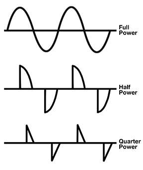
The TRIAC (Triode for Alternating Current) can conduct amperes of current in either direction when it is triggered (turned on) by a milliamp-level signal on its gate. As the heart of a dimmer, it is very efficient, and can be placed in a standard outlet box. To dim an incandescent bulb, the TRIAC-based circuit controls the point in the AC line phase where conduction begins (Figure 1). The dimming circuit is designed so turn-on can begin anywhere in the cycle, depending on use setting, but always includes zero-crossing of the cycle; it is a version of control via pulse-width modulation (PWM) control.
As a result, the filament sees pulses of voltage and thus reaches full incandescence, but for less than full time. Due to the thermal time constant of the filament, the bulb integrates the applied power, thus maintaining desired color temperature while its perceived brightness dims.

Figure 1: TRIAC-based dimming for incandescent works by allowing peak AC voltage, but using more or less of the overall 360° sine cycle in synchronization with the line zero-crossings; here, the pulse-width modulation is shown for full-, half-, and quarter-power waveforms.
Dimming LEDs
The LED is a very different load than the incandescent filament. First, it needs to be driven by a current source (typically 20 to 60 mA) rather than voltage source. While this is not difficult in itself, it does require a different supply design. Second and much more difficult, the LED is a diode-like, highly non-linear load, even more complicated than just a simple reactive (capacitive or inductive) load.
The obvious way to dim the LED is to reduce its drive (here, current rather than voltage); as with incandescents, this does not work very well, as the color purity and efficiency of the LED degrades with reduced current. A better alternative is to use PWM and adjust the full-current duty cycle to achieve desired dimming. This is an effective approach which maintains LED performance, and is used for "captive" LED designs, such as in backlighting, displays, signage, and indicators.
LEDs Meet TRIACs
TRIAC-based dimmers for incandescent bulbs are installed in countless millions of AC light switch control boxes. Even if they were not installed at time of construction, they are easily added as a retrofit if desired; they retail for around $10, and no wiring changes other than replacing the on/off switch with a dimmer unit are required.
However, as consumers switch to LED- (and CFL-based) lamps in existing dimmer circuits, there is a problem: the output of the TRIAC dimmer is incompatible with the drive circuitry within the LED lamp. Not only does it not dim the LED lamp properly, it can also cause the overall LED lamp performance to suffer (a lamp is what the consumer buys — it is the complete assembly of bulb, drive circuitry, housing, and base). Consumers expect to install their new energy-saving LED-based lamp into an existing socket, which may be on a dimmable circuit, and have it work and dim as well as the previous incandescent lamp. (Note that there is also a corresponding problem with dimmers and driving CFLs (compact fluorescent lamps) but that is another story.)
Dimming and AC Wiring
The issues go beyond the incompatibility of the TRIAC-based drive/dimmer and the needs of an LED-based lamp. The various ways that house AC wiring for lamp branch circuits is installed can also result in reduced dimming range, flickering or fluttering of the lamp, and inconsistent performance.
The reason is that most existing residential wiring to lamp circuits use two-wire lighting control without a neutral wire at the switch box (the source AC has three wires: hot, neutral, and ground); a circuit branch with a neutral wire is called three-wire lighting control. There are significant differences in performance between these two branches in how the dimmer circuitry is powered and how the dimmer synchronizes with the line voltage.
These differences are generally not an issue for incandescent lamp loads, but stable dimming and control is more complicated for LED loads. TRIAC dimmers need to synchronize their switching point with the AC line in order to work correctly. If they cannot sense the AC-line zero crossings, they lose the ability to control and dim the lamp load.
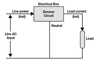
Looking at the wiring in more detail, three-wire installations (Figure 2) have line-side hot, load-side hot, and neutral wires in the electrical box. The line wire comes from the AC-power source and powers both the dimmer and the load. The load wire is connected to the lamp load to provide a return path for the power delivered to the load. The neutral connection provides the essential return path for the dimmer even when the load is disconnected or is in a state where it does not draw any current. It not only ensures that the dimmer has power to drive its own internal circuitry even when the load is disconnected or off, it also provides a clean signal of the incoming AC-power source for detection of zero-crossings and synchronization with the line. This makes for stable, reliable phase-controlled dimming.

Figure 2: The three-wire branch circuit to the lamp load includes a neutral line, while the two-wire circuit does not have that line; its absence contributes to erratic dimmer operation for LEDs although not for incandescent.
In two-wire installations, there are only line and load hot wires, and no neutral connection, with the dimmer in series between the line and the load. As a result, the dimmer must rely on the "trickle" current passing through the load to both power its own internal circuitry, as well as to detect zero-crossings for synchronization with the AC line.
When the load is an incandescent lamp, there is small but sufficient trickle load current through the filament resistance even when apparently “off,” so it is easier to synchronize to the line cycle and provide sufficient power for the dimmer’s internal circuitry. For LED lamps, however, the load current is much smaller and much less regular, and line synchronization becomes difficult. Further, the load current of LED lamps when in their off state can be quite small, so that even getting a few milliamps to power the internal dimmer circuitry can be a problem. The shortcomings of both supply and stable line synchronization will often result in lamp flickering.
Due to this problem and related issues, the National Electrical Code (NEC) in the US added a requirement in 2011 for a neutral wire in all switch boxes. However, a vast majority of existing home installations are two-wire systems without the neutral wire, so dimming circuits for LEDs must operate properly in both two- and three-wire situations.
LED Drive ICs Address the Problem
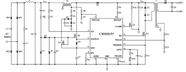
Vendors have both recognized the complex nature of the situation, and that the sophisticated function which can be built into an IC can address the problem of the dimmable LED lamp. The CS1610 family of four ICs from Cirrus Logic is an example (they are externally similar, but designed for 120 VAC, 230 VAC, and different load ratings). LED lamps built using these ICs can provide wide-range flicker-free dimming in an existing TRIAC circuit, and are compatible when connected to circuits which dim on the leading edge of the AC sine wave, as well as those which dim on the trailing edge; the lamps can also work in circuit with no dimming capability at all (Figure 3).

Figure 3: ICs in the CS1610 family from Cirrus Logic are designed to be built into the base of an LED lamp, with AC mains as the input and LEDs as the load, and provide full operational and dimming compatibility with the "chopped AC" waveforms coming from TRIAC-based dimming circuits. (Click for full size)
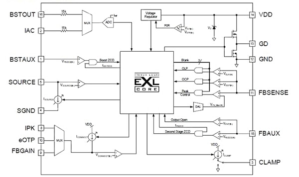
The CS1610 (for example the CS1610-FSZ) and CS1611 are designed to control a quasi-resonant flyback-topology power source in the LED lamp, while the CS1612/13 is intended to control a buck-topology supply. All four use a critical conduction mode (CRM) boost converter to maintain desired output current and also provide power-factor corrector (PFC), which is another issue when driving non-resistive loads (Figure 4). They use a complex, adaptive algorithm and digital processing engine to sense the line and load situation and then control the boost stage, to ensure dimmer-compatible operation.

Figure 4: The internal block diagram of the CS1610 shows the level of complexity needed within the IC, including a digital engine core, to act as a seamless bridge between two otherwise incompatible power waveforms and associated loads.
Summary
While it is relatively easy to dim light-emitting diodes (LEDs) using pulse-width modulation (PWM) to regulate the total current the LEDs receive, it is much more difficult to dim LEDs which are designed to be compatible drop-in replacements for the standard incandescent bulb. The ubiquitous TRIAC-based dimming circuit, which "throttles" the AC-line voltage in phase with zero crossing to provide dimming, is incompatible with the dimming-drive requirement of the LED.
Fortunately, ICs have been developed which allow the LEDs in these replacement bulbs to be dimmed properly, even when they are connected to the TRIAC-based incandescent circuit. This article has explained how TRIAC-based dimming is done for incandescent lamps, examined the requirements of LED dimming, discussed the problems due to the dimming circuitry (erratic operation, flicker, and poor dimming performance) and clarified the variations of the standard AC line wiring of the lamp branch circuit. It then showed how it is possible to build an LED-based bulb which is fully dimmable, even when used in an otherwise incompatible TRIAC circuit. The article further examined ICs from Cirrus Logic which act as a transformational bridge between the two worlds, providing a seamless, quality experience when an LED lamp is screwed into a socket or fixture on a conventional dimming circuit.
면책 조항: 이 웹 사이트에서 여러 작성자 및/또는 포럼 참가자가 명시한 의견, 생각 및 견해는 DigiKey의 의견, 생각 및 견해 또는 DigiKey의 공식 정책과 관련이 없습니다.


